Inspired by a fellow YouTuber, I wanted to build an LED display myself. Ping Pong balls should be used as the diffusing elements. This gives the display a distinct look and creates an interesting illumination. The development of the display is not yet finished, but the progress is shown as part of a YouTube video series.
Part 1 – The Body
The body of the PingPong Display was designed in Fusion360. It incorporates 331 ping-pong balls arranged in a hexagonal pattern. This reduces the inter-pixel distance which leads to a higher pixel density. The balls are attached to a laser-cut board. It ensures the correct positioning. The board consists of multiple layers made from MDF which incorporate features to attach the LEDs from underneath. The baseboard is supported by wooden bars around the perimeter of the hexagon.
| 4x | Base Board Material: HDF Size: A1 Thickness: 3 mm |
| 6x | Wooden Bars Material: Beech Size: 20×50 mm |
| Wood Glue | |
| 18x | Screws Type: Flat Hat Length: 50mm |
| 1x | Clamping Band |
| 1x | Paint Color: Black |
| 7x | LED Strip LED Type: WS2812B # LEDs: 50 each Type: String (!) LED Distance: 120 mm |
| 331x | Toothpicks |
| Hot Glue | |
| 331x | Ping-pong Balls Diameter: 40 mm |
Part 2 – Power Supply
The 331 LEDs draw up to 16,5 A of electrical power which adds up to 83 W @ 5V. Therefore, a fitting enclosed power supply with passive cooling was chosen. As it constantly draws current even in stand-by mode, a Solid State Relais is used to cut the supply of the grid if it is not required. To power the microcontroller and some other components, an additional AC-DC converter is added.
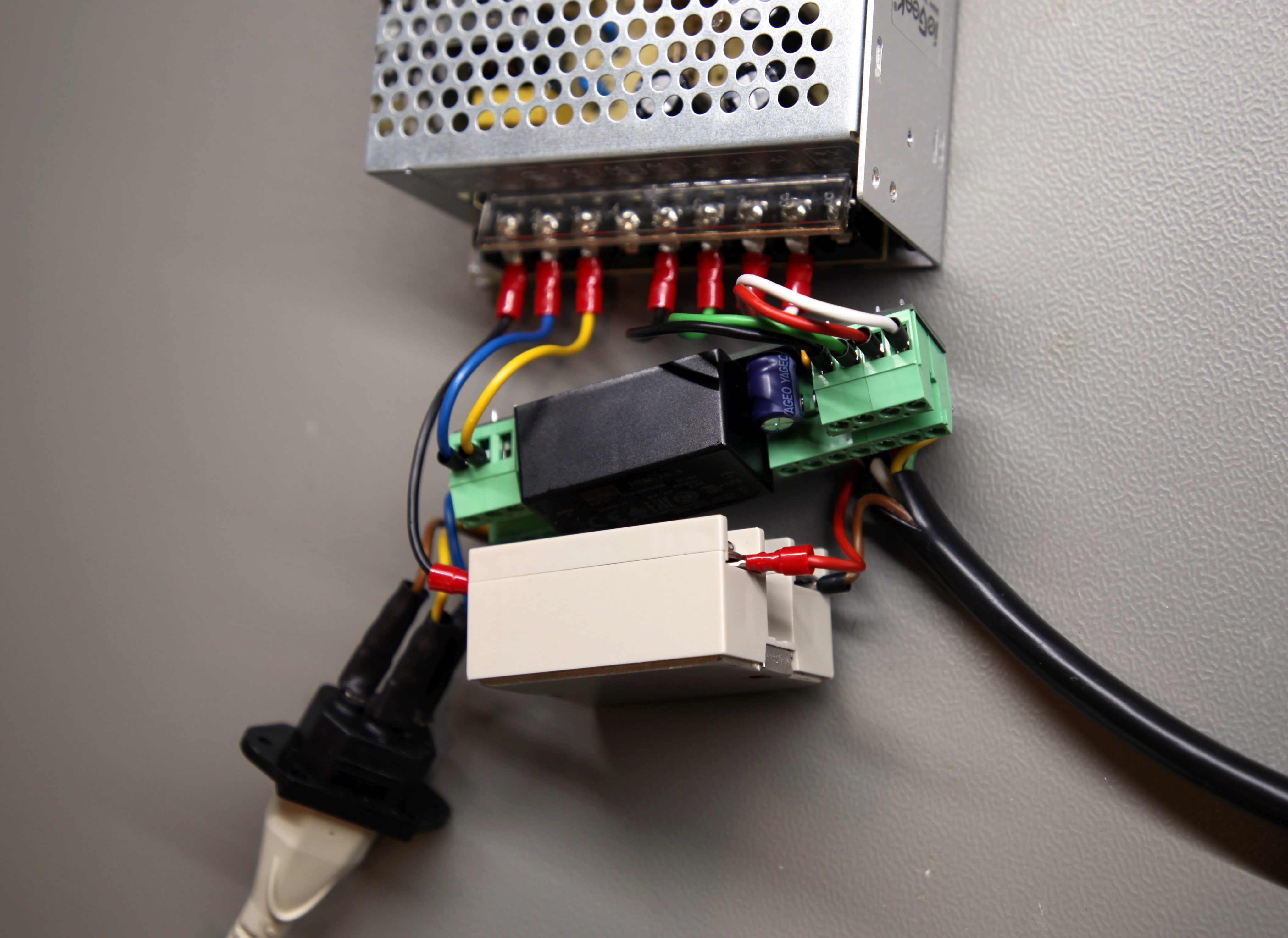
To route the power to all LEDs safely and uniformly, 4 thick wires are used to connect the controller box to the power supply. From there, 7 individual cables are connected to every 50th LED.
| 1x | Power Supply Type: HG2547 Rating: 5 V, 10 A |
| 1x | Solid State Relais Type: SSR-40 Manufacturer: Fotek Rating: 380 V, 40 A |
| 1x | Custom Circuit Board |
| 1x | AC-DC Converter Type: IRM-10-5 Manufacturer: Mean Well Rating: 5 V, 10 W |
| 1x | Screw Terminal # Pins: 7 Spacing: 5.08 mm |
| 1x | Screw Terminal # Pins: 4 Spacing: 5.08 mm |
| 2x | Screw Terminal # Pins: 3 Spacing: 5.08 mm |
| 2x | Screw Terminal # Pins: 2 Spacing: 5.08 mm |
| 1x | Capacitor Type: Electrolytic Rating: 150 uF |
| 1x | Capacitor Type: Ceramic Rating: 10 nF |
| 1x | Screwed Cable Gland |
| 1x | Inlet connector for non-heating apparatus |
| 1x | Cable Specs: 7x 1.5mm² |
| Cables | |
| Crimp connectors | |
| Heat shrink tubing |
Part 3 – Controller Unit
To control the LED’s behavior, an ESP32 microcontroller is used. It features potent computing power, lots of I/O pins, and a small form factor. But most important, it enables WiFi and Bluetooth connections which can be used to control the final display remotely. However, the design included two rotary encoders that can be used to manually input directly on the device.
Additional sensors should further extend the device’s capabilities. I decided to go for a microphone, a temperature and humidity sensor, a motion sensor, a light sensor, and a gas and smoke detector. Those additional components are hooked up to the central ESP32 making use of nearly every GPIO pin.
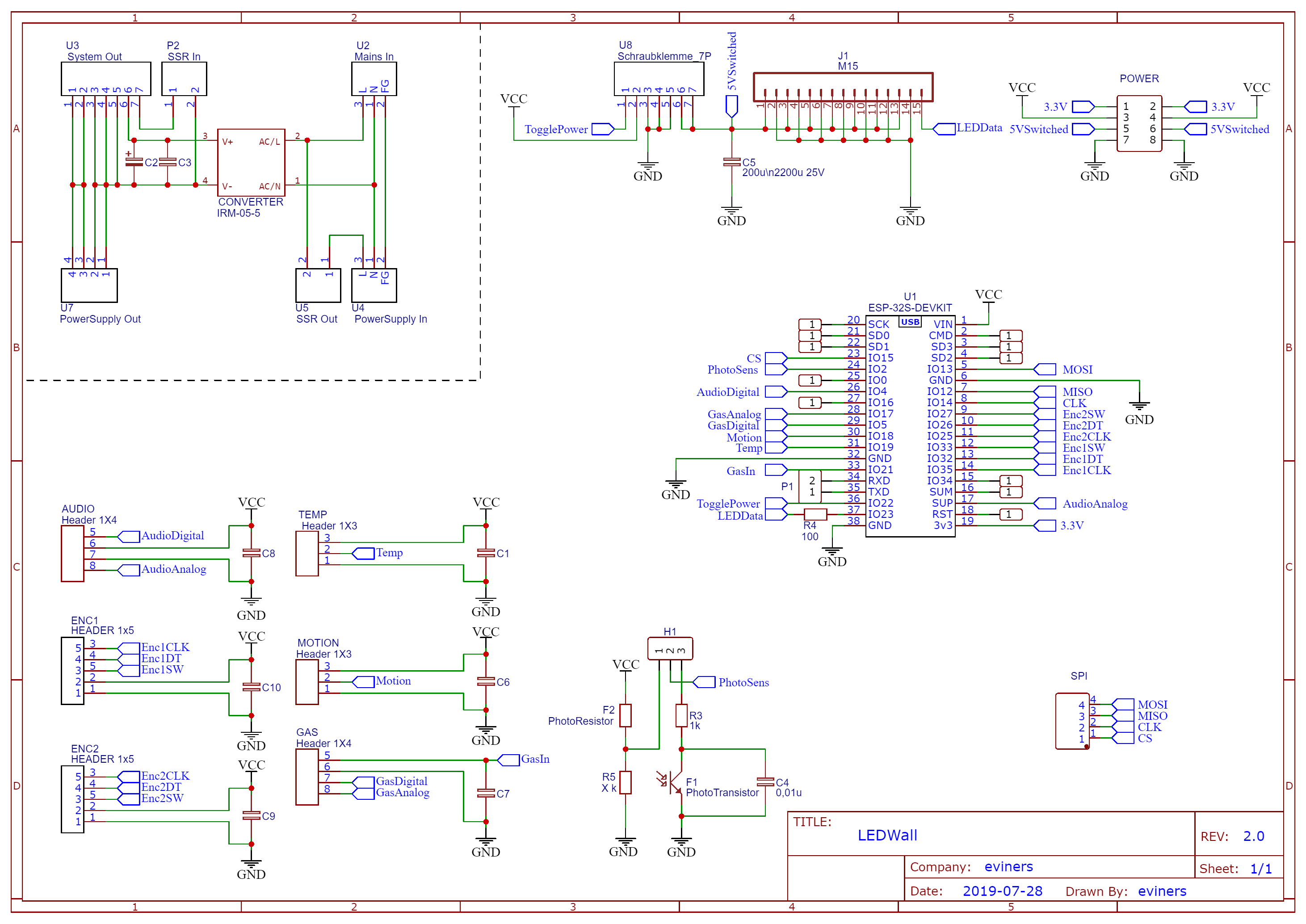
A custom circuit board is used for tedious wiring and includes all the connectors in a neat arrangement. A hexagonal case was designed in Fusion360 and printed using white PLA. The audio, temperature, and gas sensors are arranged on the perimeter while the motion sensor, light sensor, and the encoders are sticking out the front to face later users.
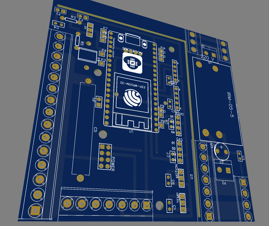
The 7-strand wire of the power supply is connected to this custom PCB as well and splits it into 7 individual 2-strand wires that are connected to the LED strings. Additionally, a data wire is connected to the first LED. The data packets are passed from one WS2812B to the next which simplifies their control.
| 1x | ESP32 Microcontroller Board Type: NodeMCU ESP-32 |
| 1x | LM393 Microphone Amplifier Board |
| 1x | DHT22 Temperature & Humidity Sensor Board |
| 2x | KY-040 Rotary Encoder |
| 1x | HC-SR501 PIR Motion Sensor |
| 1x | MQ-2 Gas Sensor |
| 1x | Screw Terminal # Pins: 15 Spacing: 5.08 mm |
| 1x | Screw Terminal # Pins: 7 Spacing: 5.08 mm |
| 2x | Pin Connectors Type: female, print # Pins: 19 Spacing: 2.54 mm |
| 3x | Resistor |
| 1x | Capacitor Type: Elec Capacity: 2000u |
| 6x | Capacitor Type: Ceramic Capacity: 100n |
| 1x | Ribbon Cable |
Part 4 – Software
As the utilized WS2812B LEDs are becoming pretty popular in the Maker Community, there are a lot of software libraries available to control them. I went with the FastLED library as it is one of the most popular ones and features simple but powerful functionalities.
The dense hexagonal arrangement of LEDs is not only a big advantage but also a major drawback on the software side. The LEDs are either used as strips or as rectangular LED matrices. A custom calculation is needed to map the position of each LED to a commonly used X/Y position. A simple LUT and a few calculations did the job in the end.
static const int linearIndices[] = {
  -1,-1,-1,-1,-1,-1,-1,-1,-1,-1,-1,-1,-1,-1,-1,-1,-1,-1,-1,-1,-1,-1,-1,-1,-1,-1,-1,-1,-1,-1,-1,-1,
  -1,-1,-1,-1,-1,-1,-1,-1,-1,-1,-1,-1,-1,-1,-1,-1,-1,-1,-1,-1,-1,-1,-1,-1,-1,-1,-1,-1,-1,-1,-1,-1,
  -1,-1,-1,-1,-1,-1,-1,-1,-1,-1,-1,-1,-1,-1,-1,-1,-1,-1,-1,-1,-1,-1,-1,-1,-1,-1,-1,-1,-1,-1,-1,-1,
  -1,-1,-1,-1,-1,-1,-1,-1,-1,-1,-1,-1,-1,-1,-1,-1,-1,-1,-1,-1,-1,-1,-1,-1,-1,-1,-1,-1,-1,-1,-1,-1,
  -1,-1,-1,-1,-1,-1,-1,-1,-1,-1,-1,-1,-1,-1,-1,-1,-1,-1,-1,-1,-1,-1,-1,-1,-1,-1,-1,-1,-1,-1,-1,-1,
  -1,-1,-1,-1,-1,-1,-1,-1,-1,-1,-1,-1,-1,-1,-1,-1,-1,-1,-1,-1,-1,-1,-1,-1,-1,-1,-1,-1,-1,-1,-1,-1,
  -1,-1,-1,-1,-1,-1,-1,-1,-1,-1,-1,0,1,2,3,4,5,6,7,8,9,10,-1,-1,-1,-1,-1,-1,-1,-1,-1,-1,
  -1,-1,-1,-1,-1,-1,-1,-1,-1,-1,22,21,20,19,18,17,16,15,14,13,12,11,-1,-1,-1,-1,-1,-1,-1,-1,-1,-1,
  -1,-1,-1,-1,-1,-1,-1,-1,-1,-1,23,24,25,26,27,28,29,30,31,32,33,34,35,-1,-1,-1,-1,-1,-1,-1,-1,-1,
  -1,-1,-1,-1,-1,-1,-1,-1,-1,49,48,47,46,45,44,43,42,41,40,39,38,37,36,-1,-1,-1,-1,-1,-1,-1,-1,-1,
  -1,-1,-1,-1,-1,-1,-1,-1,-1,50,51,52,53,54,55,56,57,58,59,60,61,62,63,64,-1,-1,-1,-1,-1,-1,-1,-1,
  -1,-1,-1,-1,-1,-1,-1,-1,80,79,78,77,76,75,74,73,72,71,70,69,68,67,66,65,-1,-1,-1,-1,-1,-1,-1,-1,
  -1,-1,-1,-1,-1,-1,-1,-1,81,82,83,84,85,86,87,88,89,90,91,92,93,94,95,96,97,-1,-1,-1,-1,-1,-1,-1,
  -1,-1,-1,-1,-1,-1,-1,115,114,113,112,111,110,109,108,107,106,105,104,103,102,101,100,99,98,-1,-1,-1,-1,-1,-1,-1,
  -1,-1,-1,-1,-1,-1,-1,116,117,118,119,120,121,122,123,124,125,126,127,128,129,130,131,132,133,134,-1,-1,-1,-1,-1,-1,
  -1,-1,-1,-1,-1,-1,154,153,152,151,150,149,148,147,146,145,144,143,142,141,140,139,138,137,136,135,-1,-1,-1,-1,-1,-1,
  -1,-1,-1,-1,-1,-1,155,156,157,158,159,160,161,162,163,164,165,166,167,168,169,170,171,172,173,174,175,-1,-1,-1,-1,-1,
  -1,-1,-1,-1,-1,-1,195,194,193,192,191,190,189,188,187,186,185,184,183,182,181,180,179,178,177,176,-1,-1,-1,-1,-1,-1,
  -1,-1,-1,-1,-1,-1,-1,196,197,198,199,200,201,202,203,204,205,206,207,208,209,210,211,212,213,214,-1,-1,-1,-1,-1,-1,
  -1,-1,-1,-1,-1,-1,-1,232,231,230,229,228,227,226,225,224,223,222,221,220,219,218,217,216,215,-1,-1,-1,-1,-1,-1,-1,
  -1,-1,-1,-1,-1,-1,-1,-1,233,234,235,236,237,238,239,240,241,242,243,244,245,246,247,248,249,-1,-1,-1,-1,-1,-1,-1,
  -1,-1,-1,-1,-1,-1,-1,-1,265,264,263,262,261,260,259,258,257,256,255,254,253,252,251,250,-1,-1,-1,-1,-1,-1,-1,-1,
  -1,-1,-1,-1,-1,-1,-1,-1,-1,266,267,268,269,270,271,272,273,274,275,276,277,278,279,280,-1,-1,-1,-1,-1,-1,-1,-1,
  -1,-1,-1,-1,-1,-1,-1,-1,-1,294,293,292,291,290,289,288,287,286,285,284,283,282,281,-1,-1,-1,-1,-1,-1,-1,-1,-1,
  -1,-1,-1,-1,-1,-1,-1,-1,-1,-1,295,296,297,298,299,300,301,302,303,304,305,306,307,-1,-1,-1,-1,-1,-1,-1,-1,-1,
  -1,-1,-1,-1,-1,-1,-1,-1,-1,-1,319,318,317,316,315,314,313,312,311,310,309,308,-1,-1,-1,-1,-1,-1,-1,-1,-1,-1,
  -1,-1,-1,-1,-1,-1,-1,-1,-1,-1,-1,320,321,322,323,324,325,326,327,328,329,330,-1,-1,-1,-1,-1,-1,-1,-1,-1,-1,
  -1,-1,-1,-1,-1,-1,-1,-1,-1,-1,-1,-1,-1,-1,-1,-1,-1,-1,-1,-1,-1,-1,-1,-1,-1,-1,-1,-1,-1,-1,-1,-1,
  -1,-1,-1,-1,-1,-1,-1,-1,-1,-1,-1,-1,-1,-1,-1,-1,-1,-1,-1,-1,-1,-1,-1,-1,-1,-1,-1,-1,-1,-1,-1,-1,
  -1,-1,-1,-1,-1,-1,-1,-1,-1,-1,-1,-1,-1,-1,-1,-1,-1,-1,-1,-1,-1,-1,-1,-1,-1,-1,-1,-1,-1,-1,-1,-1,
  -1,-1,-1,-1,-1,-1,-1,-1,-1,-1,-1,-1,-1,-1,-1,-1,-1,-1,-1,-1,-1,-1,-1,-1,-1,-1,-1,-1,-1,-1,-1,-1,
  -1,-1,-1,-1,-1,-1,-1,-1,-1,-1,-1,-1,-1,-1,-1,-1,-1,-1,-1,-1,-1,-1,-1,-1,-1,-1,-1,-1,-1,-1,-1,-1
};
I further adapted the Adafruit_GFX, Framebuffer_GFX, and FastLED_NeoMatrix libraries for my project. Basic graphic primitives like rendering lines, shapes, or text became possible. Additionally, I developed custom letters to display text on the device using the least amount of LEDs possible.
Next, all the sensors had to be included. Some were more straightforward than others.
The motion sensor has a digital output, which can be configured to stay HIGH for a specified amount of seconds once it registers a movement. In combination with a UTC time, this turns the display into a custom nightlight.
The audio sensor offers simple analog and digital output which roughly reflects the environment’s noisiness. Unfortunately, the measurements are not that exact. So in the end, I implemented a simple clap and double clap event that can be used to activate the display or switch its mode.
The gas sensor is a bit more difficult. It offers a digital and an analog pin that changes its output value depending on the gas (e.g. Methan) concentration in the air. But to do so, the internal heating wire needs to heat up for a certain amount of time before the measurements are correct. The module’s 5V pin is therefore switched on by the microcontroller in defined intervals, to regularly check the environment’s gas concentration.
The temperature and humidity sensor requires serial communication over a single bus to receive the data. Fortunately, the Adafruit DHT-sensor-library does this job for me, so it is easy to receive the data.
I had the most problems with the two rotary encoders. Finding a proper encoder library that deals with debouncing and uses interrupts did cost a lot of trial and error. In the end, integers for both rotary values as well as interrupts when pressing the knobs are implemented.
In the end, I have a big library that offers a lot of functionality for the device. I am going to combine this into some automation (clap to turn on display) and a web interface. This can be used to trigger different functionalities remotely and to display the data I want.