
A few years ago, I became aware of a project called Sisyphus. It is a form of Kinetic Art, in which a ball rolls through sand, creating and erasing beautiful patterns. The designs created were fascinating and the constant transformation meditative. In 2016, one maker stepped up and started a Kickstarter campaign to bring these artistic masterpieces into private people’s homes. This was the birth of sisyphus-industries.com, an American workshop that now sells high-quality coffee tables with a kinetic artwork in its core. Since then, I wanted to have one on my own but the prices (ranging from 600-9000$) and the shipping costs deferred this wish for years.
In recent years, a few DIY variants popped up on YouTube channels and I watched their builds carefully. Additionally, I got more and more skilled in 3D printing and digital fabrication. In principle, one could hack together a rudimentary Sisyphus Table with the components of a 3D printer. And as I was looking for a new hobby maker project at the end of 2021, I decided to give it a try.
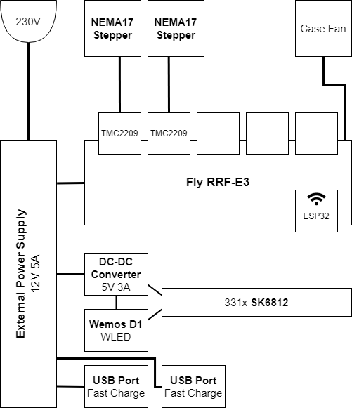
My general conditions were to replace a coffee table in my living, with a maximum size of 600x900mm. I wanted it to work similarly to the commercial versions, with automatic pattern creation and colorful illumination, as well as smartphone controls. I knew I would need a 2-axes-gantry and the 2 required stepper motors were already laying around from a previous project. Additionally, I needed a motherboard intended for 3D printers, that I could use. In the end, I opted for a just-released Fly RRF-E3 board with TMC2209 Silent Stepper Motor Drivers. I added a 12V external desktop power supply and the main electrical system was finished.
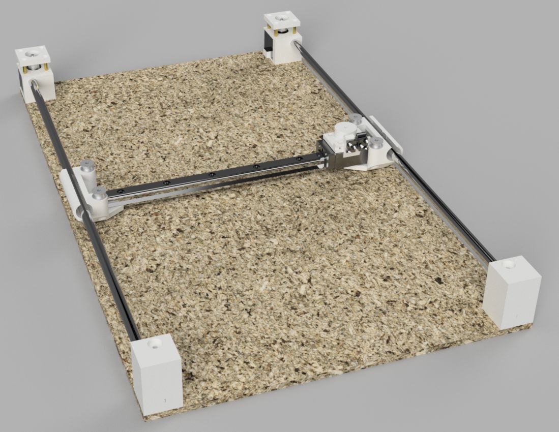
Next up was the XY-gantry: I decided to use a configuration called H-Bot. This is rarely used in 3D printers as it is unprecise without quite bulky hardware. But for the intended use case, simplicity came far before precision. While I decided to use a linear rail for the Y-axis (needs to stay upright), the X-axis was created from two ball bearings on linear shafts (later opted for cheaper aluminum rods). Connectors and mounts were then 3D printed after several iterations of modeling and testing. A GT2 timing belt is wound around the steppers and drives both axes individually. This was a simple and cheap version to create a proper XY-gantry.
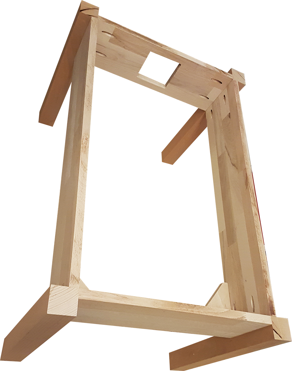
Then I had to create the wooden body of the table. I use beech wood in the form of rectangular bar strips for the legs and solid wood panels for the sides. All were cut according to my 3D model and joined using pocket holes. For the inlay, two plywood sheets were used, one holding the gantry, and the other for the box with the sand. The latter was built from simple wooden strips and lined with white false leather. Every part of this stack was damped so that vibrations do not travel through the wooden body. I added a strip of custom addressable LEDs (SK6812) in aluminum profiles to the sand box for illumination using WLED.
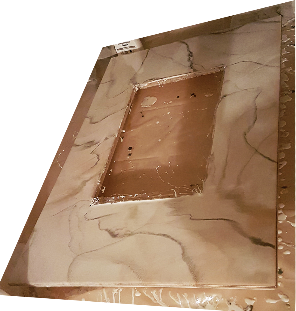
For the tabletop, we decided to try something a bit fancier. I took a 12mm plywood and made a cutout for a custom-ordered shatterproof glass. Then we used epoxy resin to create a marble-like surface. The first layer penetrated the wood for stabilization and filling any air traps. The second layer was mostly white in different tones and shimmers, as well as some greyish veins that were faded using a hot air gun. The third layer was again different whites, but the veins can shine through. After this process, the table was hand-sanded for weeks (up to 600 grid sandpaper) until the upper surface had an even, slightly rough surface.